|
Archives
and Download - Archives
Changing
the tube in a Spectronika Copper Vapour laser
L. Michael
Roberts
Abstract
The Spectronika copper vapour laser is a low cost, high power, air cooled
laser. The laser uses a sealed tube design which lasts for approximately 800
hours of operation before the tube requires replacement. This paper
covers step by step instructions for the tube change procedure.
DETAILED INSTRUCTIONS
1/ PREPARATION
- Place the laser on a clean flat working surface with plenty of space
around it so you will have room to work.
- You will need Philips and flat-blade screwdrivers and an 8mm wrench or
a small adjustable wrench.
CAUTION: This laser operates at high voltages. Laser tubes can act
as a capacitor, holding a charge for some hours after they are last
energised. As a precaution, you should insure that the laser has been turned
off and unplugged for 6-10 hours before performing this procedure. You
should ground the frame of the laser and use a test lead to briefly connect
the electrodes of the laser tube to the grounded frame to insure there is no
residual charge on the tube.
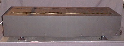
2/ OPEN THE LASER
- Remove the cover of the laser and set it aside along with the screws
that hold it in place. The laser tube, inside the heater jacket, is now
accessible.
3/ LOCATING THE ELECTRODES
- At either end of the laser tube you will find small
"side-arms" below the tube. These terminate in a metal cap
with a bolt extending from each cap - these are the electrodes which
supply the high voltage to the tube.
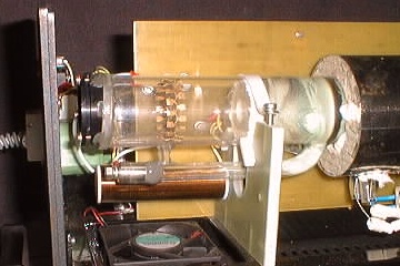
The photo above shows the side-arm and electrode at the reflector end of
the tube - there is a similar assembly at the output end of the tube.
4/ ELECTRODE DISASSEMBLY
- Carefully unscrew the nuts on the electrodes at each end of the laser
tube using an 8 mm wrench or a small adjustable wrench.
- Each electrode has a nut, a lock washer, a flat washer and a ring
terminal with an attached wire. Set the nuts and washers aside and slide
the ring terminals off the electrodes.
- Use care so as not to bang the main body of the tube with the wrench,
or apply excess torque to the electrodes.
The photo above shows the bolt extending from the electrode after the
wire has been removed. The white wire and ring terminal can be seen hanging
down below the electrode [just above the cooling fan].
5/ HEATER JACKET CLAMPS
- There are two clamps that hold the heater jacket in place around the
laser tube.
- Remove these screws, nuts and washers and set them aside.
- Carefully open the clamps and remove them from the heater jacket.
The photo above shows the clamps after they are unscrewed and opened and
before they are removed from the heater jacket.
6/ OPENING THE HEATER JACKET
- Carefully remove the top cover of the heater jacket by lifting it
straight upwards.
- There are two segments of insulated packing material, one at each end
of the tube. These may fall off when the cover is lifted.
- Recover these and put them aside with the top of the heater jacket.
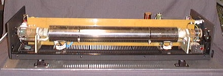
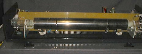
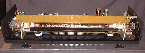
The tube is now exposed.
In the photo above, you can see the exposed tube and the packing material
around one end of the heater jacket. This laser was dropped and broken
during shipping - normally the tube should be intact.
7/ TUBE HOLD-DOWN STRAPS
- The tube is secured in place by means of an insulated strap screwed
into an insulated stand at each end.
- Unscrew and remove the back screw completely from each tube stand.
- Now slack off the front screws 3-4 turns.
- The holding clamps can now be rotated so that they are no longer over
the tube.
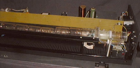
In the photo above, you can see the holding clamp has been rotated so
that the tube is now free and can be removed from the laser.
8/ REMOVING THE TUBE
- Carefully remove the tube by lifting it straight up and away from the
laser.
- Take care not to disturb the small glass thermocouple tube which is
located at the output end of the laser tube.
- Set the old tube aside on a clean dry surface.
9/ UNPACKING REPLACEMENT TUBE
- The new laser tube is wrapped in plastic inside a foam filled
cardboard box. This is in turn inside a foam filled wooden box.
- Carefully remove the wrapped tube from the cardboard box being careful
not to put any stress on the tube and not to bump the side-arms against
the boxes as it is removed.
CAUTION: All laser tubes are fragile and should be handled with
extreme care. The Spectronika tube has the output optic permanently
installed and aligned - care must be taken not to bump or disturb this
alignment in any way.
Do NOT handle the new tube with your bare hands, handle it through the
plastic wrap or while wearing disposable surgical gloves or cotton gloves to
avoid contamination of the tube surface.
10/ UNWRAPPING THE TUBE
- Set the tube on a clean working surface being sure not to bump the
side-arms in the process.
- Carefully cut the tape holding the plastic in place with a sharp knife
so that the tube can be unwrapped.
- Leave the tube in the plastic for now, provided you can freely remove
the plastic from around the tube. This is to protect the optics from any
dust and dirt until the tube is installed in the laser.
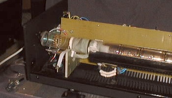
11/ TUBE ORIENTATION
- Determine the output and reflector ends of the tube - the output is
the clear glass end while the reflector has a black mirror assembly.
- The output should face the aperture in the front end of the laser,
while the reflector end faces the 3 small holes in the back plate.
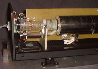
The photo above shows the clear glass window at the output end of the
tube facing the aperture in the front plate from which the beam is emitted.
12/ INSTALLING THE TUBE
- Holding the tube by its plastic wrap, carefully place it on the two
insulated stands with the side arms straight down - take care not to
bump the side-arms against the stand as it is put in place.
- Do NOT handle the new tube with your bare hands, handle it through the
plastic wrap or while wearing disposable surgical gloves - this is to
avoid contamination of the tube surface and optics with skin oil
residue.
13/ TUBE CENTRING
- Make sure the side arms are centred in the space below the plastic
insets on which the tube rests in the stands at either end.
- Swing the insulated hold down clamps back over the tube and secure
them in place with the screws.
- Do NOT over-tighten these screws as excess pressure will crack the
tube - when the tension is correct, the tube can be rotated in it's
stands only with some effort and can not be rotated freely.
14/ THERMOCOUPLE
- Check to see the the small glass thermocouple tube is parallel to the
tube in the bottom quadrant at the output end of the tube.
- The thermocouple should not touch the tube, but be held in place by
the insulated packing material and the laser tube so that it is parallel
to the tube.
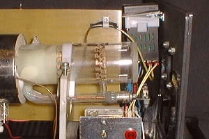
The photo above shows the new tube clamped in position in the stands and
ready for the installation of the heater jacket.
15/ REPLACING HEATER JACKET
- Place the two pieces of insulated packing material in position at
either end of the tube.
- Carefully place the cover of the heater jacket in place, making sure
the tabs on the jacket top hold the insulated packing material in place
and against the tube such that they form a seal around the tube in
conjunction with the two pieces of insulated packing material that
remained in place in the bottom segment of the heater jacket.
16/ CLAMP THE HEATER JACKET
- When the top of the heater jacket is in the correct position,
re-install the two clamps around the heater jacket.
- Put the bolts in place, slip the washer over the bolt, and thread on
the nut.
- Make certain that the clamps are positioned in such a way that they do
not block any of the vent holes in the heater jacket.
- Tighten the clamps until the heater jacket is firmly held in place -
do not over-tighten as you will distort the heater jacket.
17/ INSTALLING THE TUBE LEADS
- To re-assemble the connections to the electrodes at each end, first
place the ring terminal on the electrode bolt, followed by the lock
washer, followed by the flat washer, followed by the nut.
- Hand tighten the nuts at each end.
18/ TIGHTENING THE ELECTRODES
- Using the 8 mm wrench or adjustable wrench, tighten the bolts on each
electrode - use care in this procedure so that the wrench does not
contact the main body of the tube, or that the tightening of the the
nuts does not cause the tube to rotate in it's mount.
CAUTION: Do NOT over-tighten these nuts as this can cause damage
to the electrodes or break the tube.
19/ FINAL INSPECTION
- Inspect the laser and make sure that all the parts are back in place
and accounted for.
- Check the hour meter on the rear of the laser and write down the date
and the hours shown on the meter on a strip of masking tape.
- Affix this to the inside of the back plate of the laser so you have a
record of the tube change.
- Power up the laser and wait until the high voltage is automatically
applied.
- Carefully inspect the electrode assembly [without getting to close] to
insure that there is no arcing in the connections.
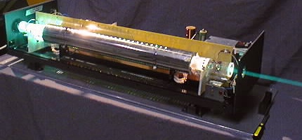
The photo above shows the newly re-tubed laser under test - the masking
tape with the tube change information can be seen on the back plate of the
laser.
20/ REPLACE THE COVER
- Once the laser has been tested for 15-20 minutes, shut it down and
allow it to cool.
- Replace the main cover on the laser and screw it in place.
The laser is now re-tubed and your can enjoy another 800 hours of emerald
green and gold beams.
The procedure above takes about 90 minutes if you work slowly with care
and caution, double checking each step. It can be accomplished in under an
hour if you are experienced and have all the tools at hand.
DISCLAIMER:
Some of the information in the Backstage area is provided by the persons or
companies named on the relevant page(s). Laser F/X does NOT endorse or
recommend any products/services and is NOT responsible for the technical
accuracy of the information provided. We provide this information as a
service to laserists using the Backstage area.
[ Introduction
| Archives | Download
]
|