|
|
Self
Starting Phase Converter
This schematic for a
self starting 20 kVA phase converter, to convert single phase to three phase
power, was contributed by Jake Wolfe - yagmaster1@yahoo.com
INTRODUCTION:
If you have ever found yourself in need of three-phase power where only single-phase service is available, and have checked into the prices for having three-phase service installed at your location, chances are you were rather
unpleasantly surprised. Where I am, for instance, having power pole transformers installed and the underground wire run to the house would have totaled a bit over $50,000. That is a pretty steep price to pay just to run an entertainment laser or a piece of three-phase shop
equipment.
The only realistic solution to the average laserist is to use the existing single-phase service to produce three-phase power. The most efficient, and by far the cheapest method to accomplish this task is by using a rotary phase converter.
A rotary phase converter is simply a three-phase motor that uses the motors windings and a bank of capacitors to create a phase shift in the incoming power, as well as generate a third phase, much like a normal generator would use shifting magnetic fields to create electricity. Basically its like using a single phase motor to power a three-phase generator, but instead of having a separate motor and generator, both units are combined into one. The physics behind everything that is happening is quite complex, and is well beyond the scope of this simple discussion,
who's purpose is simply to explain and instruct you how to build a reliable, tested, safe, and affordable means to operate three-phase equipment.
The phase converter in this discussion was built from a 30 h.p. three-phase motor, wired to run at 208-250 volts. Using this size of motor, well balanced (within 5% for voltages and phase angles) three-phase power at about 30 amps per leg can be generated. At 208 volts, this works out to be just a little under 20kVA, and considering that most small- to mid-frame ion lasers producing 5-10 watts of light consume somewhere in the neighborhood of 12kVA, this is more than enough power. Note that I said that the phase converter can supply 20kVA of well balanced three-phase power. I have run two Spectra Physics 165 ion lasers at full current at the same time on this phase converter, a power consumption of 24kVA, and when I measured the leg voltages and phase angles, everything was still within 10% of being perfect three-phase power. This is still quite acceptable three-phase power, just not quite as clean as if one laser was running
from it.
DESCRIPTION:
Okay, now that the basic explanation is out of the way, lets get down to the nitty gritty details of parts, construction, and operation. Take a look at the materials list in the schematic, and I will explain what each part is. Part K1, the potential relay, part number 685744-90014, is
manufactured by Mars Replacement Components, 250 Rabro Drive East, Hauppauge,
NY, 11788. Alternatively, G.E. also makes one, part number 3ARR3K25S3. Its function is to sense the voltage on the generated phase leg, L3. It is normally closed, as you can see, but once power has begun to be generated on L3, disengages the motor start capacitors by opening the contactor K2. The contactor is simply a very large relay that can be purchased from most industrial electrical supply companies, and is a standard 208-240V, 150A, normally open two-pole unit.
The motor start capacitors are of the A/C electrolytic type because they are not used to continually run the motor, but rather are used only to start the motor. This type of capacitor can not withstand prolonged usage, and so is only used to start the
motor. Running the motor requires oil filled capacitors, specially designed to withstand the abuse of continuously charging and discharging at line frequency. I purchased both types of capacitors from a respected phase converter manufacturer, GWM. Their website
address is http://gwm4-3phase.com
Note that the motor run capacitors have only 1/10 the capacitance of the start capacitors, but are the same size (approximately 3 inches diameter by 5 inches tall). I did try to run the motor on a single start capacitor, thinking I could save space by only using one capacitor instead of 10.
DON'T TRY THIS!!! The capacitor became blazing hot after only a few minutes, and began spewing foul smelling chemicals from the rubber plug on its top. Needless to say, the capacitor was completely destroyed, not to mention the extreme fire hazard it posed in the process.
After hooking up the appropriate motor run capacitors, I found things to be much happier, the capacitors only being slightly warm after several hours of use. The next item on the parts list is the three phase motor itself. After contacting several of the top phase converter manufacturers in the U.S., I found that the ideal motors for this application were manufactured by Toshiba and Tatung between 1990 and 1994, before the federal mandate for more energy efficient motors. The reason you should look for a non energy efficient design is that, when used in a phase converter application, energy efficient motors tend to overheat, possibly even burning up the motors coils. I don't know why this is, but I know that it is true, having seen pictures of melted rotors from phase converters using this type of motor.
Cast iron endbells are very much preferred over aluminum, because the iron is much harder,
as they have less tendency to deform after years of use. I say this because more than likely, the motor you will be picking up will be used, coming from an industrial environment. If the bearings have sagged down in their mounts slightly because of endbell deformation, your motors rotor will no longer be exactly centered in the stator, and this can cause large phase and voltage imbalances. The cast iron frame and endbells also help to contain and direct the motors magnetic fields better than aluminum, serving to improve the three-phase power's
characteristics.
The motor size you should look for is a NEMA 286T frame, 30 horsepower, and the configuration of the motor should be four-pole 1800 RPM, 208-250 volts, as seen in photo
1.
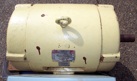
Photo 1 - NEMA 286T frame, 30
horsepower motor
Please note that this motor is fairly large in size, weighing 500 pounds or more, so before anything, plan out where you will be putting the phase converter, and figure out how you will move it if you need to. Roll around carts are not recommended for
operating the phase converter, because the starting torque from the motor is quite substantial. If you start the motor on something that can move, chances are that it will end up in a different place than it was before you started it, and maybe rip out some high voltage, high current wires in the process. The final piece of electrical equipment needed to complete the phase converter is a buck/boost transformer, such as the one in photo
2.
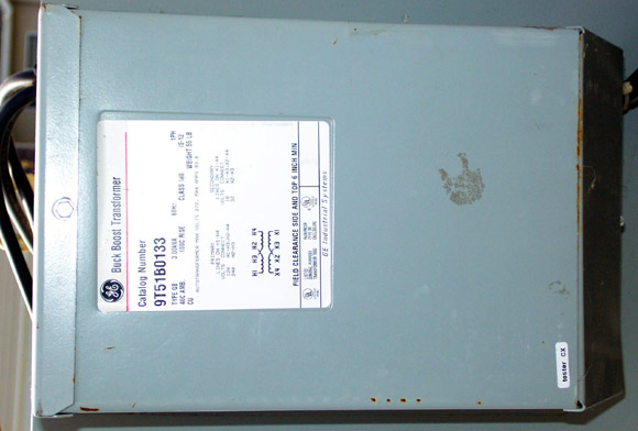
Photo 2 - GE part number
9T51B0133 Buck Boost Transformer
These can also be ordered from almost any industrial electrical supply house. The unit I purchased is manufactured by General Electric, catalog number 9T51B0133, and is capable of handling 25kVA continuously when used in a buck/boost configuration. The purpose of this transformer is to raise or drop the line voltage before it enters the phase converter, so that your equipment is seeing the proper three-phase voltage. The single-phase voltage going into the phase converter is the same as the three-phase voltage coming out. This particular GE unit provides a 32 volt drop, so the incoming 240 volts is reduced to 208 volts. Please note that this transformer does not serve to isolate the phase converter in any way from the incoming line. An isolation transformer that could handle this much power would weigh just about as much as the motor, and cost a few thousand dollars. This particular transformer weighs in at 55 pounds, and cost less than
$200 US$.
CONSTRUCTION:
Before construction, you need to make sure that the electrical service from which you will be running the phase converter has the capacity to do so. This can be done by calling your power service provider and asking them how to read the meter that serves your location. Minimum service requirements would constitute having 200 amp service, and you need to be absolutely sure that the rest of the loads on the panel will not exceed 100 amps BEFORE the phase converter is turned on You will also need to install a 100 amp circuit breaker in your breaker panel, and run wires from it directly to the transformer and phase converter, or to a disconnect, then to the transformer and phase converter. Minimum wire
gauges should be 4 gauge, or preferably 2 gauge for both wires carrying single-phase power from the breaker to the phase converter.
For all ground wires, 8 gauge is sufficient. All internal wiring in the phase converter
which caries three phase and the cables carrying the three-phase power to your
equipment which will be carrying three phase power should be 4 or 6
gauge wire . All of the electronics can be enclosed in a 16x16x6 inch metal junction box, which is available at any electrical supply house. I mounted the box directly to the motor, so that the entire unit can be moved as one piece. All of the components and wire fit neatly inside the box, as seen in
photo3.
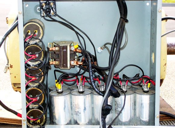
Photo 3 - Interior of the
components cabinet
The transformer can be mounted on the outside of the junction box, as seen in photo
4, or if you wish, you could purchase a slightly larger box which could enclose the electronics as well as the transformer. When making connections between the capacitors, use 10 or 12
gauge wire, and make sure all spade connectors are clean and corrosion free. Any bad connections can cause considerable localized heating, ruining the capacitor. I found that the easiest way to connect a number of medium
gauge wires coming from the capacitors was by purchasing a crimp lug for 8
gauge wire (available at any auto parts store), and that way you have a very tidy connection to your contactor as well. All capacitors in a bank should be daisy chained together, and connections to the contactor can just be made to the caps on either end of the bank, as seen in photo
3.
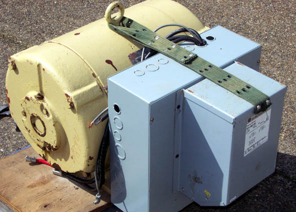
Photo 4 - The complete
phase converter with motor, electronics box and buck boost
transformer
Most
of the information and ideas in the Hobby Archives have been contributed
by hobbyists and experimenters. If you have any comments or ideas to
share, please contact us by E-mail.
DISCLAIMER:
Some of the information in the Backstage area is provided by the persons or
companies named on the relevant page(s). Laser F/X does NOT endorse or
recommend any products/services and is NOT responsible for the technical
accuracy of the information provided. We provide this information as a
service to laserists using the Backstage area.
[ Introduction
| Hobby
Archives | Hobby
FAQ | Laser
Construction ]
|