|
|
Laser
Hobbyists - Laser Construction
Many people have expressed an interest
in building their own lasers, particularly green DPSS lasers. The
first step in building a 532 nm laser is to produce the
necessary IR laser beam for frequency doubling. This
article on building an IR laser pump cavity was
contributed by Bob, the resident solid-state laser guru on
alt.lasers.
Pump
Cavity
Photo note: In order to provide as
much detail as possible, very large photographs were
provided to illustrate this article. They are too
big to post on this web page so smaller versions are shown
here. There is a link at the bottom of the page that
will allow you to download a .zip file archive of the
original, large format, high resolution photographs.
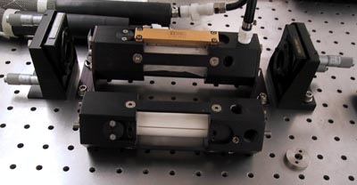
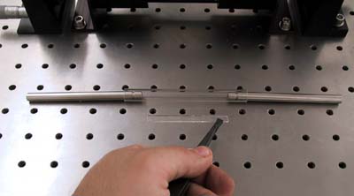
img_0633
In the foreground a 3 fold symmetry pump assembly is visible. in the background a single
sided pump housing is seen. In the 3 sided pump housing, no pump diodes are present.
The line in the white ceramic on this housing is a glass waveguide.
The pump diodes 'look' at this waveguide, which serves to transmit light through the walls of a ceramic defuse
reflector. Clearly visible on either sides of this
waveguide (on the end blocks of the pump housing), are rubber
O-rings that mate up to the cooling path of the diodes.
Cooling water comes in and is split into three separate paths for the pump diode
assemblies, then is directed back the other direction to cool the
laser rod.
In a configuration such as this, a thermal switch should be placed on the back of each diode heat sink, such that the power
supply will turn off in the unlikely event that cooling water flow is
obstructed in any one of the diode heatsinks. In the single sided illumination housing this is obviously not an
issue, and water flow integrity can be monitored by overall water flow through pump housing.
The set screws and rounded anodized aluminum disk seen in the three sided pump housing
are portions of the water cooling channels machined into the housing.
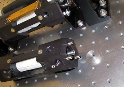
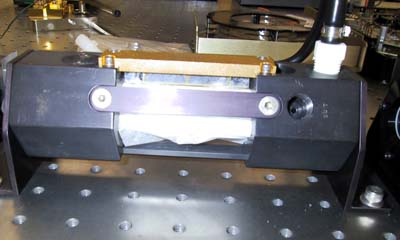
img_0632
In this photo, the rod holder and outer O-ring seal can be seen.
The rod holder used is designed to keep the faces of the rod dry by small
Teflon O-rings. The outer O-ring seal defines the water flow path for the rod, along with the inner
O-ring seen in the next photo.
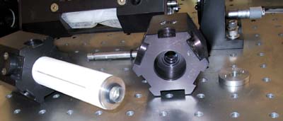
img_0634
In this photo, a close up of the inner O-ring seal is seen.
The stainless disk seen at the end of the ceramic reflector compresses the
O-ring around the glass flow tube against the end block of the pump housing.
This defines the water flow path for the rod.
The ceramic diffuse reflector is also seen in this photo.
For the diffuse reflector to be effective, a minimum wall thickness of 7 to 8 mm should be used.
Also seen is the waveguide that couples light into the inside of the pump cavity where the
YAG rod normally resides
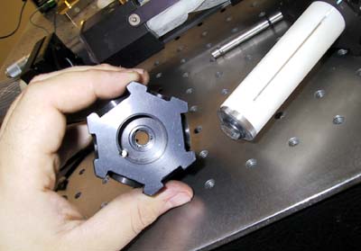
img_0636
One of the most important portions of the pump housing is this alignment pin.
A notch in the end stainless steel ring is clearly visible.
This notch continues to the ceramic reflector, although it is not clearly
visible in the photo. This notch provides for indexing the rotation
of the diffuse reflector, to keep it in the correct relationship to the pump diodes.
Also seen in this photo is a groove provided to allow a seat for the inner
O-ring. The additional grooves provide a 'step' in the inside diameter of the housing that hold the rod holder.
The fit of this rod is very snug near the end of the pump housing block, where the
outer O-ring is located. This ensures a good mechanical support for the rod.
The inside diameter then increases in steps inside the pump block
to allow for a sufficient water flow path to cool the rod.
A note on the construction of the slit in the diffuse reflector for the waveguides:
As can be seen in this photo, the slit where the waveguide
resides is somewhat longer than the waveguide itself.
The ceramic was clamped down, while the 1.05 mm thick slit was cut in it with a 1"
diameter diamond wheel saw. As the saw can not cut a square face, the slit was
purposely cut a bit short for the waveguide on the inside
diameter of the diffuse reflector; and a bit long for the waveguide
on the outside diameter of the diffuse reflector. A narrow file, or a piece of sand paper folded over a small
stainless steel ruler was then used to lengthen the slit in the
outside diameter of the cylinder.
Once the slit is enlarged to allow the waveguide to be
freely inserted, the small overspill on the outside
diameter allows for a convenient pocket for a highly viscous
UV cured optical cement to grab the edges of the waveguide.
The use of a very viscous cement and these small overspill 'pockets' is rather
important; if a less viscous cement is used, or if the waveguide is glued in by the optical faces, the index
of most cements will not allow TIR [Total Internal
Reflection] to keep the pump light in the waveguide thus reducing
efficiency. In some cases, enough power is
transmitted to fracture the ceramic due to excess heat dissipation.
It is also important to note that the glass waveguide must fit freely into this slot. if the fit is
difficult or needs ANY encouragement, you will most likely
have scratched the waveguide, reducing it's efficiency.
If the slot is opened up too far, there will be unacceptable slop in the position of the
waveguide. For this reason it is advisable to get an extra waveguide made as a dummy that can be used
to gauge the proper thickness of the slot.
img_0638
Here we see the internal flow tube, rod mounts and waveguide,
separated from the pump chamber. The waveguide is being held in position as it would be 'looking' at the rod in the center of the flow
tube.
img_0639
Here we see a finished cavity with the ceramic diffuse
reflector and it's waveguide. The waveguide is wrapped
in lens paper to protect it from dust etc. However the location of the pump diode array looking at
the waveguide in the diffuse reflector can be seen.
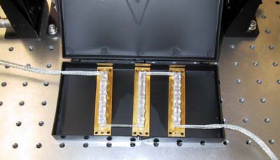
img_0640
Pump assembly for 3 sided pump cavity... note the alignment of the diode
bars. The bars must be aligned to a tolerance of a fraction of a
millimeter. Each pump diode assembly looks at it's own waveguide, only a millimeter thick. by the time the pump light hits
the waveguide, it's width is several hundred microns, allowing for a
positional error of the centerline of the pump assembly to be no more than a few
hundred microns on either side of the centerline of the
waveguide.
This is the most critical specification of the entire assembly.
Gross misalignment will cause light to spill past the waveguide, heating the
ceramic reflector, possibly to the point of fracture.
Sources for materials
-
The ceramic used is called Maycor.
Other machineable ceramics by the trade name
Spectralon is also available, however I strongly prefer
Maycor. This material is available in any size and
shape you could imagine from Ceramic Products Inc,
Palisades park, NJ, (201) 947-0336
-
The rod holder used is an industry standard holder used in may lasers. the rod is 4mm in diameter.
Aa holder from a Control Laser, Laser Applications,
Lee Laser, or the like would suffice. If one can
not be scrounged, then buy a 4mm rod holder from TJ
Sales, Sanford Florida, (800) 561-6164
-
The glass flowtube used in this particular head has an
inside diameter 1 mm larger than the outside diameter of the rod holder
and a wall thickness of 1mm. I do not list specific dimensions
in this case, because there are some minor differences
in 4mm rod holders that might require one to use a different
id tube.
Normally Pyrex can be used, and is very cheap HOWEVER a 1mm
thickness of Pyrex has only a transmission of about 92% for
808nm light. if you want to build this on the cheap or you want to build a prototype for the
least amount of money, use Pyrex. TJ Sales listed above can provide flowtubes to your specified id / od
and length requirements. If you would like higher
efficiency, use a flow tube made out of bk-7.
-
The rod used was a .9% Nd rod. this is not the optimal dopant concentration for a diode pumped laser,
nor for a diode pumped laser with such an inhomogeneous
pump profile as a single sided cavity. However, since the light from the waveguide is highly
divergent, and mostly not absorbed in the first pass at the rod, the diffuse reflector does a good job of
homogenizing the pump light distribution.
Most YAG you will find on the market is between .9% and 1.2% Nd... a
knowledgeable surplus dealer may be able to identify the concentration based on the laser the rod was
used in, or if you are lucky by it's original packing.
The rod used in this case was 4mm diameter by 80mm in
length. YAG is not self absorbing, so there is no reason not to leave yourself with
a lot of overspill on the ends... it makes assembling things
in the rod holders much simpler.
-
The glass waveguide I used was a 1mm thick, 8mm deep, and 68 mm long piece of bk7. the entrance and
exit faces do not need to be anti-reflection coated, but it naturally will lead to a
more efficient laser if they are. Any optic house can fabricate
these waveguides. I had VLOC of Port Richey, Florida
(727) 375-8562 fabricate these waveguides (and the bk7 flowtube).
If you use someone else, expect a price of about $100
US$ ea for a quantity of a few.
-
The optical adhesive used is Norland NOA63
available from Thorlabs at (973) 579-7227
Defenses
between this design and a highly efficient one
As mentioned before, this design is every bit as good as
an homogenizing pump light, even when using single sided
illumination. If you want the best results, you really should use something like
0.6%Nd. Most optics houses don't stock this material.
At the time of this writing, VLOC had some 0.6%ND material
sitting on the shelf from a previous order (quite possibly mine :) ).
A proper rod might cost you a few hundred dollars as opposed to
$100 US$ for a surplus rod.
In this design, the inside diameter of the diffuse reflector is simply fine ground and honed at the local machine
shop. This does not provide the most efficient surface on the inside of the pump chamber.
If you are familiar with amateur telescope finishing, then you may be able to come up with a way of polishing
the inside diameter of this tube. A steel rod in a drill, with a polishing
compound soaked felt will work, but takes patience... when a good polish is
achieved Maycor will have a very glassy look to it.
The better the polish the more efficient a diffuse reflector you
have.
If you do not want to use a waveguide or flow tube that is
anti-reflection coated, this is fine, however, keep in mind that
paying for anti-reflection coatings is just about the same as getting 20% more
pump diode light... If you have the same optics house make your waveguides and flowtube, then ask them if they will hold the
pieces till they do an 808 nM anti-reflection coating run for another
customer; that way you don't have to pay for coating runs for your 3 or 4 little pieces of
glass. For an efficient coating, at least 3 runs are needed... 3 runs to get the entire
diameter of the flow tube, and 2 of the runs for each side
of the waveguide (entrance and exit faces). If you have an
optics house just do the coating runs for your parts, you may expect to pay upwards of
$1500 to $2000 US$ - if you get lucky and find someone who will deal
with you, you might get your stuff coated for a few hundred
bucks!
Finally, the waveguides in my more advanced design
cavities are a little bit more exotic. The waveguide
is not a constant 1mm thick, but tapers from 1mm at the entrance face to 300 microns at the exit.
This waveguide is much more expensive, and requires a more exotic
machining process to be used on the diffuse reflector to properly hold the tapered
glass waveguide in place. Such an improvement is beyond the scope
of this home build pump chamber.
A single sided pump cavity with a short resonator and
240 watts of pump diode power yields about 85w of 1064nm in a
acceptably homogenous high order mode beam. Power output will drop to about
50 watts using a Pyrex flowtube and non anti-reflection coated surfaces.
Coming
next...
Turning this into a cheap green laser...
PHOTOS: Download the detailed
high resolution photos - PumpCavity.zip
(3,063 KB)
Most
of the information and ideas in the Hobby Archives have been contributed
by hobbyists and experimenters. If you have any comments or ideas to
share, please contact us by E-mail.
DISCLAIMER:
Some of the information in the Backstage area is provided by the persons or
companies named on the relevant page(s). Laser F/X does NOT endorse or
recommend any products/services and is NOT responsible for the technical
accuracy of the information provided. We provide this information as a
service to laserists using the Backstage area.
[ Introduction
| Hobby
Archives | Hobby
FAQ | Laser
Construction ]
|