|
Laser
Show Systems - Pinouts
This
section contains pinouts of many popular boards and components that are
used in laser show systems.
DISCLAIMER:
The pinouts shown here were contributed by manufacturers, vendors and
individuals. While every effort has been made to insure accuracy,
LaserFX.com can not be responsible for any errors or omissions.

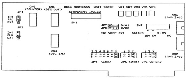
New
Method Lasers - X29 pinout and Signal Specifications
Pinout for the connectors on the X29 full length and
short interface cards. This is NOT an official New Method Lasers document -
for complete details, contact NML@laser-light-show.com

Connector CN2:
Analogue X-Y galvo outputs
| Board Pin |
DB25 pin |
Function |
Usage |
| 13 |
7 |
X out (+/-) 8V |
Bipolar output to X galvo |
| 14 |
20 |
X ground |
Analogue ground |
| 15 |
8 |
Y out (+/-) 8V |
Bipolar output to Y galvo |
| 16 |
21 |
Y ground |
Analogue ground |
Connector CN3:
Digital RGB and trigger outputs
| Board Pin |
DB25 pin |
Function |
Usage |
| 1 |
1 |
Trigger Out |
TTL out (see note 1) |
| 2 |
14 |
Trigger Out |
TTL out (see note 1) |
| 3 |
2 |
Trigger Out |
TTL out (see note 1) |
| 4 |
15 |
Trigger Out |
TTL out (see note 1) |
| 5 |
3 |
Trigger Out |
TTL out (see note 1) |
| 6 |
16 |
Trigger Out |
TTL out (see note 1) |
| 7 |
4 |
Trigger Out |
TTL out (see note 1) |
| 8 |
17 |
Trigger Out |
TTL out (see note 1) |
| 9 |
5 |
Red low |
TTL out (see note 2) |
| 10 |
18 |
Red High |
TTL out (see note 2) |
| 11 |
6 |
Green low |
TTL out (see note 2) |
| 12 |
19 |
Green High |
TTL out (see note 2) |
| 13 |
7 |
Blue low |
TTL out (see note 2) |
| 14 |
20 |
Blue High |
TTL out (see note 2) |
| 15 |
8 |
N/C |
Not used |
| 16 |
21 |
Blanking |
TTL blanking signal |
| 17 |
9 |
Ground |
Digital Ground (see note 3) |
| 18 |
22 |
Ground |
Digital Ground (see note 3) |
| 19 |
10 |
+5 VDC |
Vcc for TTL buffers etc (see note 4) |
| 20 |
23 |
+12 VDC |
Vcc for mini relays etc (see note 4) |
NOTES
1/ Pins 1-8 can be used either to drive eight
actuators with digital (on/off) signals, or can be digitally decoded to give
255 lines of digital (on/off) control.
2/ For colour control use the G, G and B High lines in digital mode to get 7
colour control. Each of the the Red low and high signals can be decoded to
give 4 levels of brightness for each colour.
3/ The digital ground and analogue grounds are separate. Do not use the
digital ground with analogue signals and vice versa.
4/ CAUTION: do not short these pins to ground or any other voltages as it
may cause damage to your computer power supply. Insulate from any nearby
pins and fuse at 1 amp max.
Connector CN4:
Digital trigger inputs
| Board Pin |
DB25 pin |
Function |
Usage |
| 1 |
1 |
Trigger in |
TTL input (see note below) |
| 2 |
14 |
Trigger in |
TTL input (see note below) |
| 3 |
2 |
Trigger in |
TTL input (see note below) |
| 4 |
15 |
Trigger in |
TTL input (see note below) |
| 5 |
3 |
Trigger in |
TTL input (see note below) |
| 6 |
16 |
Trigger in |
TTL input (see note below) |
| 7 |
4 |
Trigger in |
TTL input (see note below) |
| 8 |
17 |
Trigger in |
TTL input (see note below) |
NOTE: The input lines can be used as 8 individual
inputs for triggering or can be encoded with an external device to give 255
trigger combinations.
DISCLAIMER:
Some of the information in the Backstage area is provided by the persons or
companies named on the relevant page(s). Laser F/X does NOT endorse or
recommend any products/services and is NOT responsible for the technical
accuracy of the information provided. We provide this information as a
service to laserists using the Backstage area.
[
Introduction - System
Design - Scanning Systems
- Support
Equipment - Laser
Graphics - Show
Production - Pinouts ]

© 1996-2002
Laser
F/X International and LaserFX.com 905-523-7669 - All rights reserved.
Logos and trademarks are the property of their respective owners - used
by permission.
|