|
Laser
Show Systems - Scanning Systems
HOW TO TUNE
TO THE ILDA TEST PATTERN
By Bill Benner and Patrick Murphy, Pangolin Laser Software
Note: The information reproduced here was originally published in
the Winter 1994 edition of Laser Effects The Light Show Quarterly and is
reproduced here by permission.
The ILDA test pattern was adopted on 24 June 1992. At the date of
publication in Laser Effects, ILDA has not yet published any instructions
for using the test pattern. There are still elements of the test pattern
which are undocumented anywhere. To help fill the information gap, Laser
Effects prevailed upon Pangolin Laser Software to write this article. These
are not official instructions -- they reflect Pangolin's experience only.
This article is for intermediate and advanced laser display personnel. It
assumes you have experience with scanner tuning procedures in general, and
your system in particular. Because all scanner amps are different, the
article cannot give specific information on which way to turn controls, etc.
|
This is a drawing of how the ILDA test
pattern should look when properly tuned. Although it says "12K"
at the lower left, you tune when it is running at one of the two ILDA
standard speeds: either 12,000 (12K) of 30,000 (30K) points per second.
|
Picking Your Tuning Speed
The first consideration is what speed you wish to use in
tuning your particular scanning system. Most closed-loop scanner amps can
run at 12K. This speed can also be reached by open-loop scanners using
"acceleration" feedback scanner amps.
The 30K speed is for CT-6800 scanners and for General Scanning G-120
scanners being driven with "turbo" scanner amp designs.
This pattern will not work with some older scanner amps designed for
small-step response only. For these amps, software never permits a large
jump between points in an image. Such amps may blow fuses or may be damaged.
The ILDA test pattern is designed for systems were points can jump any
distance.
Scan Size (angle)
The second consideration in tuning is the scan size. The
absolute maximum scan size is the rated scan angle limit. In the case of
G-120 scanners, at 12,000 Points Per Second (PPS) the limit is 40 degrees
peak-to-peak. For G-138 scanners, the nominal limit is 76 degrees.
Normally your maximum scan size will be below this limit. For example, in an
auditorium the screen may be far away, so you can scan only 20 degrees. When
tuning for this venue, output the ILDA test pattern so that the outer square
is scanning at 20 degrees before starting the tuning procedure.
However, in many cases you want the maximum scan angle. Tune to about 10%
under this, to give yourself a margin of safety. For G-120 scanners, this is
roughly 35 degrees at 12K PPS.
If you are tuning faster, the maximum scan angle is reduced. For both
CT-6800 and G-120 scanners, the limit is about 25 degrees at 30K PPS. Once
you tune to a certain safe angle, scanner response is then flat up to that
angle. This means that a full-size image will not distort when it gets
smaller (on a zoom-out, for example). However, the image may distort if it
is enlarged past the maximum tuning size.
For this reason, tune to the largest safe angle that you'll encounter at
your studio or show site.
There is one time when you do not start tuning at the at
the largest safe angle. This is when the scanner amps are in an unknown
state. In such a case, begin with a small image. Tune to get is "in the
ballpark" before increasing the size.
There are two sets of test in the ILDA Test Pattern. The "A" set
is for scanner alignment, and the "B" set is for blanking
alignment.
"A"
tests: Scanner alignment
A1: Correct scanner speed. The circle should be the
same size (width and height) as the square. It should touch the midpoint of
each side of the square, as shown.
This is the most important requirement for speed
matching. If the circle is smaller than the square, then the scanners not
being driven as hard as they should be. Increase servo a bit, then increase
damping to compensate for any over or undershoot (see above or glossary for
an explanation of gain. offset, servo and damping).
On most scanner amps, the image size will also change, so adjust gain to
keep the same image size. Continue increasing servo and adjusting damping
(an gain as needed) until the circle just touches the square's sides.
If the circle is larger, then the scanners are being driven too
"hot" beyond the ILDA spec. Decrease servo and adjust damping (and
gain if required) to match the circle to the square.
You will probably find that the circle is a bit sensitive. This is actually
good -- if it wasn't sensitive then there would be no point in tuning to it!
You can be assured that if your scanners show the test pattern properly,
then other scanners tuned using the same speed will match your scanners.
A2: Correct damping. Corners of the square should be
sharp, with no overshoot or undershoot.
This is the most important requirement for good
looking images. The damping control is the primary control for setting
corners. As you tune, adjust the scanner amp damping back and forth. Watch
the corners of the square go to far (overshoot) or not far enough
(undershoot). You need to over then under tune to get a feel for when the
corners are correct. The procedure is similar to tuning an analogue radio
receiver, where you go back and forth until you find the clearest signal.
When adjusting damping, it is easiest to switch to a separate frame with a
7/8 size quadrature square. Don't use a full-size quad square, since you
need a little headroom in case of overshoot.
A3: Correct Phase (same scanner speeds). The circle
should be circular, not elliptical or pulled to one side.
This is easiest to do when your scanner mirrors
are the same size. Unfortunately, some laserists have one mirror smaller
than the other, so the scanner with the smaller mirror can go faster. There
is no point to this. Diagonals will distort, and images will look different
as they rotate.
You want both scanner mirrors travelling at the same speed and with the same
response, so use the same size mirrors. As a bonus, this means you only have
to stock one mirror size.
A4: Correct XY Orientation. The "Y" should be
at the top; the "X" should be at the right.
If your scanner amp has invert switches, use these
to get the correct orientation. You can also use controls in your console or
computer software, but the best place to get the orientation right is in the
scanner amps (if possible).
A5: Correct Gain. The outer box shows the limits of the
scanner.
As discussed earlier, set the maximum scan size
for your screen, before doing final tuning.
A6: Correct Centering. The "+" marks the center
of the screen.
"B"
Tests: Blanking alignment
These tests were originally developed for
scanner (galvo) blanking. They can be used for adjusting any type of
blanking.
If you software offers this feature, adjust the blank timing or blank shift
slider to get the blanking point B1 roughly correct. Then, adjust the gain,
offset and damping of your blanking device (if you use scanner blanking).
B1: Correct Blanking Speed. The upper and lower
horizontal lines meet at the small vertical line.
B2: Correct Blanking Damping. Adjust blanking damping
(if you have scanner blanking) so the two horizontal lines are equally
spaced from the small vertical line.
B3: Correct Blanking Gain and B4: Correct Blanking
Bias. The fifth dot in this group should be barely visible; the sixth dot
should be completely blanked. Also the lines at B1 should approximately meet
at the vertical line.
This is only for those using Laser Fantasy of
similar pulse-width modulation scanner techniques. Most AOM and PCAOM
systems can show the sixth dot with no problem. A few AOM or PCAOM systems
may have built-in filters that emulate the slow rise and fall of scanner
blanking. If so, the B3 test should be used to fine-tune the filter.
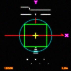
At slow speeds, (lower points
per second) the circle remains outside the square.
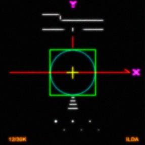
At the proper, or rated, speed,
the circle must be just inside the square – it should touch the midpoints
of the square's sides, and it should remain circular (not oval or tilted).
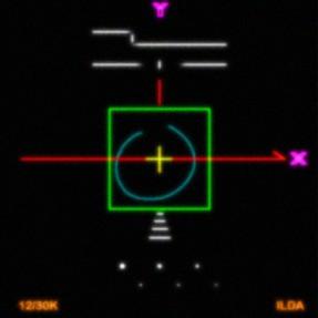
At faster-than-rated speeds, the circle will be smaller than the square.
Other Considerations
It can not be stressed enough: Although you tune to the
ILDA test pattern at 12K or 30K, you do NOT have to project your images at
this speed. You probably will set your scanning speed slower, for example to
8K of 30K. Otherwise, you'll be putting too many points at sharp angles and
corners.
Pangolin suggests that you pick a standard scanning speed and stick with it.
Your choice of speed will be dictated by the galvo/amp combination you own.
A standard speed makes it easier for you, especially of you trade with, or
purchase frames from others using the same speed.
If you have other test patterns, such as the ubiquitous Laser Media pattern,
they may not look as good at the 12K or 30K speeds. If so, you can use these
test patterns to help determine what your everyday scanning speed should be.
It may seem obvious, but there are no differences between computer graphics
systems when it comes to single-frame output such as test patterns. If
software A shows the ILDA test pattern as 12K per second, software B will
look the same when showing that frame, at that speed, on the same projector.
In fact, for any given frame (e.g., set of points) and speed, all systems
will output identical points. This is how you can tune the same as a
colleague across the country.
Some software systems don't provide the scan rate in points per second. This
is unfortunate, since there is little reason to tune to the ILDA 12K or 30K
standards if you don't know how fast you're running. Use an oscilloscope or
ask your vendor to determine your absolute point rate. If your system uses
the older measurement of microseconds per point, the formula is: 1/sec. For
example, 80 microseconds is .00008 sec. Using the formula, this is 1/.00008
or 12,500 PPS. The ILDA 12K speed is 83 microseconds per point.
The theory behind the circle-and-square tuning is that the square has many
points while the circle has a few. The square will hold it's shape at fast
speeds, but the scanner/amp system has trouble with the circle. If scanning
systems were perfect, then the circle would be larger than the square -- the
way it was digitised. But since the scanners don't have a perfect response
the standard is arbitrarily set to have the circle be the same size as the
square. The sizes are not necessarily setting anything exact (such as a 3 dB
roll-off pint); they are mostly serving as a fast reference standard for
in-field tuning.
The ILDA Test Pattern is not the ultimate testing method. Pangolin believes
that a set of scanner test frames, each optimized for a particular feature,
is best. However, the ILDA Test Pattern is a good single-frame pattern, and
of course, is the only reference standard in the industry. While you might
be able to get some performance improvement using other patterns, smaller
angles, etc., it is better to be not quite perfect but to be compatible with
the rest of the industry.
Thanks to Casey Stack, ILDA Technical Standards
Committee chair who provided Laser Fantasy's documentation on their test
pattern (on which ILDA's is based). The A and B notation and structure have
been taken from that document.
Download
a copy of the ILDA Test Pattern [10 Kb]
Download a
copy of the ILDA B test pattern [11 Kb]
NOTE:
Since this article was written, ILDA has developed
a second test pattern for use with 30K scanners,
and has published a document that details the
tuning procedure in more detail. See the ILDA
Test Pattern article.
DISCLAIMER:
Some of the information in the Backstage area is provided by the persons or
companies named on the relevant page(s). Laser F/X does NOT endorse or
recommend any products/services and is NOT responsible for the technical
accuracy of the information provided. We provide this information as a
service to laserists using the Backstage area.
[
Introduction - System
Design - Scanning Systems
- Support
Equipment - Laser
Graphics - Show
Production - Pinouts ]
|