www.LaserFX.com Home Page - CLICK HERE

  Home Page >>> Backstage Area >> Laser Show Systems > Pinouts

Search LaserFX.com - CLICK HERE Site Map - CLICK HERE
LaserFX.com Home Page
Backstage.LaserFX.com
Laser Safety
Laser Hobbyists
Laser Show Systems

Introduction

System Design

Scanning Systems

Support Equipment

Laser Graphics

Show Production

Pinouts

 
Standards and Practrices
Laser F/X Newsletter
Unclassified Ads
Business Issues
Laser Show Discussions
Archives and Download
Laser Show Resources
Updates Page - CLICK HERE
Member Services - CLICK HERE
LaserFX.com Banner Ads - CLICK HERE
About Laser F/X - CLICK HERE
Contact Us - CLICK HERE


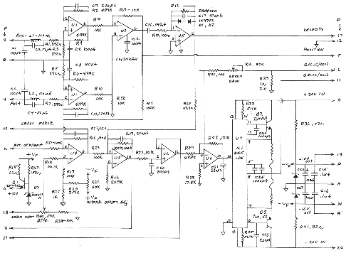
Laser Show Systems - Pinouts

DISCLAIMER: The pinouts shown here were contributed by manufacturers, vendors and individuals. While every effort has been made to insure accuracy, LaserFX.com can not be responsible for any errors or omissions.

Tropel single channel scan amp card

Tropel scan amp diagram
Click on the diagram to see a larger version

Card edge connector pinout and controls on the Tropel single channel scan amp. This amp is a 'clone' of the GS amplifier and is found in the used/surplus market. This is NOT an official Tropel document - for the latest info, contact Tropel directly.


Card edge connector

Tropel Amp Pinouts (Revision B - 44 pin edge card connector).

  • Letters go from Z to A from left to right with the component side UP and the edge connector toward you.
  • Numbers go from 1 to 22 from left to right with the component side DOWN and the edge connector toward you.

Pins not listed can be presumed to have no connection.

Pin Number Signal description
A, B and Z Power ground
3 Position Sensor minus (-)
4 Position Sensor plus (+)
8 Position Sensor - Ground
6 Position Sensor Power
18 Signal Input
N External Offset Input (leave open if not used)
M Servo error output for testing (oscilloscope tuning)
5 Position error output for testing (oscilloscope tuning)
17 Velocity error output for testing (oscilloscope tuning)
11 Galvo coil Output (high side or positive)
L Galvo coil Return (low side or negative)
A +20 VDC Power Input
20 -20 VDC Power Input
   

NOTES

1/ Connect Galvo AGC lead to position sensor ground. Note on some cards position sensor ground is not connected, connect instead to normal ground.

2/ Fuse one and fuse two are 2A long AGC type.


CONTROLS

Trimmer controls, going from edge of card towards heatsink (L to R) viewed from the component side.

1 Damping control
2 Gain control (input attenuation - image size control)
3 Offset control
4 Servo control


DISCLAIMER: Some of the information in the Backstage area is provided by the persons or companies named on the relevant page(s). Laser F/X does NOT endorse or recommend any products/services and is NOT responsible for the technical accuracy of the information provided.  We provide this information as a service to laserists using the Backstage area. 

 [ Introduction - System Design - Scanning Systems - Support Equipment - Laser Graphics - Show Production - Pinouts ]


© 1996-2008 Laser F/X International and LaserFX.com - All rights reserved.
Logos and trademarks are the property of their respective owners - used by permission.