|
|
Laser
F/X On-line Newsletter - Special Reports


Monday,
May 31 1999
Scanner
Wars
Scanning systems were a major topic
of hallway discussions at Laser F/X '99. With three new offerings, one of
which promised much higher speeds, there was a lot of intrigue and drama in
the air. From the E-mail sent out days before Laser F/X '99:
|
News
Flash! - Another Laser F/X '99 FIRST!
World's first 60Kpps Laser Light
Show to debut at Laser F/X '99!
Brought to you jointly by Cambridge Technology and New Method
Lasers Inc., the WORLDS FIRST 60k pps laser show module will be
shown this Sunday night (May 30th), during the Brewster Awards at
Laser F/X '99.
The scan head will employ the new Cambridge 6210 scanners, the
first scanners in the world to routinely produce 45-65 kpps
images. The controller will be the LCN-3D system, one of the few
controllers in the world to be able to scan at these blinding
speeds.
Fasten your seat belts!
|
The Catweazle scanners from MediaLas delivered on their promise of fast
scanning and offer the lowest cost ILDA 30K scanning in the industry at
$1,000 US$ retail. They are shipped configured in an X/Y mount and with
pre-tuned scan amps that incorporate their own power supply so
implementation is simple and easy.
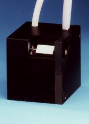
30K Catweazle scanner from MediaLas
The Cambridge 6210 galvos were said to be able to project 60K images and
there was a great deal of discussion about them before the demo during the
Brewster Awards. The demo proved unsatisfying to many as it consisted of a
module playback.
While it was very artistic and certainly put the scanners through their
paces, the playback did not provide any proof of the speed claims. There was
much skepticism and laserists preferred to wait until they could see the
ILDA Test Pattern before rendering their opinion.
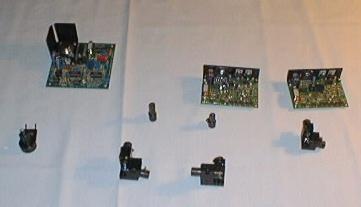
Cambridge Technology scanners
and amps on display at the Trade Show
What to look for in
the ILDA Test Pattern
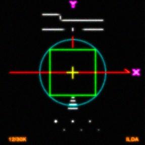
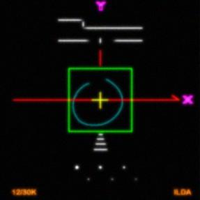
What the assembled laserists wanted to confirm was the most important
part of the ILDA Test Pattern, which consists of a circle around a square
(test pattern images courtesy of Patrick Murphy).
|
|
| At slow speeds (lower points
per second), the circle remains outside the square. |
|
|
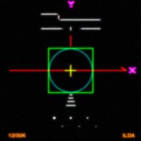
| At the proper, or rated, speed,
the circle must be just inside the square - it should touch the midpoints
of the square's sides, and it should remain circular (not oval or tilted). |
|
|
|
At faster-than-rated speeds, the circle will be smaller than the square. |
Another aspect of the ILDA Test Pattern is the width of the scan angle is
during the test. To meet the ILDA 12K standard, the test pattern must meet
the circle-in-the-square test at 15 degrees optical scan angle. To meet the
ILDA 30K standard, the angle must be "about 8 degrees optical or
less". It is generally agreed that scanners faster than 30K must show
the ILDA Test Pattern at around 8 degrees.
There appears to be some confusion, because the acid test of scanners is not
whether they can merely display laser frames running faster than 30K. Just
about any scanner can accept signals running faster than 30,000 points per
second. Even most parts of the ILDA Test Pattern can look acceptable at
faster-than-rated speeds, except for the circle-in-the-square test. But the
circle-in-the-square test is the main element of the ILDA Test Pattern!
(Incidentally, it is not a perfect test, since it measures scanner response
at just one point on the scanner's performance curve. But it is the only
well-defined and agreed-upon test in the laser show industry.)
In summary, laserists are looking to see how fast a set of scanners can
correctly reproduce the circle-in-the-square of the ILDA Test Pattern --
when the circle just fits inside the square -- while being projected at a
around 8 degrees scan angle -- scanner-to-screen distance is 7.1 times the
width of the projected test pattern.
Testing the Cambridge
6800s and 6210s
At the What's New seminar, the 6210's were put through their paces using
the ILDA Test Pattern. A number of technical problems prevented them from
reaching their full potential. These included prototype
driver cards that were not yet fully optimized to 60+k, and a
smaller-than-optimum power supply with only basic heat sinking for the
driver amps.
Discussions with Bob Ash and the Cambridge representatives led to the
conclusion that when the 6800's were introduced they were only 24K scanners.
In short order they were tweaked to 30K with some users currently running
then at 40+K tuning. Bob Ash and Cambridge believe that with a bit more work
on tuning and power supply issues, the 6210 may reach the 60K speed that
Cambridge's computer analysis indicates is possible.
The surprise of the conference was Pangolin's announcement and demonstration
of their after-market modification of the popular Cambridge 6800 scanners to
reach ILDA 50K at 7 degrees. Pangolin demonstrated two 25K shows running
simultaneously from one scanning set as well as the scanners flawlessly
reproducing the ILDA test pattern at 50K. The shows were running from a
standard Pangolin QuadMod32 board (not the new, faster PCI-bus board). The
scanners were four-year-old Cambridge 6800H's (not the newer 6800HP).
The Pangolin software is adjustable in integer increments so it was not
possible for them to show the scanners running at exactly 50K. They were
able to demonstrate the ILDA Test Pattern at 48K with the circle just
outside the square and at 55K with the circle well inside the square thus
validating the contention that the scanners were tuned to ILDA 50K.
Cambridge 6210 Update
- 03 July 1999
On the IRC chat of 16 June, Phil Barrows of Cambridge Technology was our
special guest to discuss scanner issues and particularly the new 6210
scanners. During the chat, Phil stated that he had validated the 6210
scanners could reach speeds of 60K+ and had scope photos to prove it. Here
are the photos and Phil's comments on each photo:
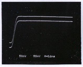 |
Photo #1:
Who: Mike Thanos, Perry Bakalos, Steve Sequeira, Martina Casey,
Phil Barrows
What: 2x6210, 2x67821, w/3mm X/Y mirrors for 60° Optical, peak
to peak, X & Y Position signal response
When: 6/11/99
Why: Small angle DC step time, ~1.6° (Opt.), ~150uS
|
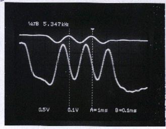 |
Photo #2:
Who: Mike Thanos, Steve Sequeira, Martina Casey, Phil Barrows
What: 2x6210, 2x67821, w/3mm X/Y mirrors for 60° Optical, peak
to peak, X & Y Position signal response
When: 6/11/99
Why: ILDA test pattern, ~4° Optical, -3db frequency response
5.347KHz=64.164Kpps
|
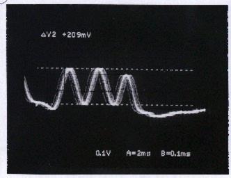 |
Photo #3:
Who: Mike Thanos, Steve Sequeira, Phil Barrows
What: 2x6210, 2x67821, w/3mm X/Y mirrors for 60° Optical, peak
to peak, Y-axis Position signal response
When: 6/11/99
Why: Similar set-up as #2, -3db amplitude measurement
|
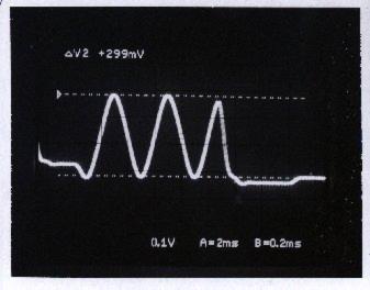 |
Photo #4:
Who: Mike Thanos, Phil Barrows
What: 2x6210, 2x67821, w/3mm X/Y mirrors for 60° Optical, peak
to peak, Y-axis Position signal response
When: 6/11/99
Why: Similar set-up as #2, same as #3, except lower point output
rate, beginning amplitude measurement.
|
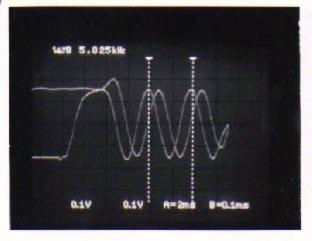 |
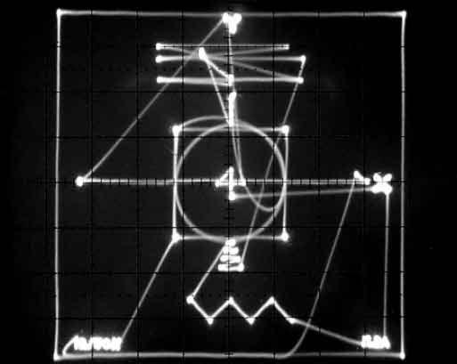
Photo #7:
Who: Steve Sequeira, Phil Barrows
What: 2x6210, 2x67821, w/3mm X/Y mirrors for 60° Optical, peak
to peak, X & Y Position signal response
When: 6/25/99
Why: -3db frequency response, ILDA test pattern, ~4° Optical,
5.025KHz=60.3Kpps in ILDA test pattern terms.
Note the second measured peak precedes the second vertical
measurement bar, making 5.025KHz of –3db response (or ILDA
60.3Kpps) a conservative measurement.
|
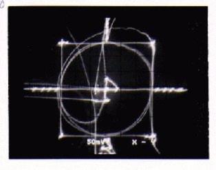 |
Photo #8:
Who: Steve Sequeira, Phil Barrows
What: 2x6210, 2x67821, w/3mm X/Y mirrors for 60° Optical, peak
to peak, X & Y Position signal response
When: 6/25/99
Why: Same set-up as #7, scope X/Y
|
By themselves, Photos 2 through 4 do not explicitly document the phase
relationship between X & Y, nor do they prove the scan retains a sine
shape, as is required for a true -3db measurement and proper use of the
ILDA test pattern. These shots alone require some measure of faith that the
test is properly executed.
Photos 7 & 8 were questions touched on during Wednesday's chat. I
believe Greg (and perhaps Bill) made a few remarks on the subject, though I
don’t have my log. These could have been captured in the first session,
but I was pressed for time and did not think to take these specific shots.
So, Photos 7 & 8 remove that subjectivity. These two photos also show
that not only is the scanner -3db response higher than is needed for ILDA
60Kpps, but also that the circle response still exceeds the boundaries of
the square. I could have touched up the tuning a bit, but felt it
unnecessary. For the record, the pattern on the wall looked considerably
better than Photo 8.
Having said all that, it is also worth saying this: "Cambridge
Technology makes no recommendation for or against regular use of the 6210 at
ILDA 60Kpps at this time."
Pangolin TrueK 50
Scanners Update - 07 July 1999
These oscilloscope photos show four-year-old Cambridge
6800 scanners with the Pangolin TrueK 50 modification. The ILDA Test Pattern
is being output at 52,083 points per second, at an angle of 6 degrees
optical.
This is slower but wider than the Cambridge-tuned 6210 oscilloscope photo #8
(60K at 4 degrees). We believe the 6800 scanners we used could also be tuned
to 60K/4ş. However, we did not re-tune as we wanted to show performance
typical of a TrueK 50-tuned system.
The photo below points out some features of the TrueK 50 modification.
Here is the entire ILDA Test Pattern on the scope, so you
can see all features. Careful readers will note that this is the correct
orientation. The original Cambridge scope photo had the X axis flopped;
Pangolin followed this in making our close-up photo, to make comparisons
easier.
Links - Quick Links
to Report Pages
In order to present as many pictures as possible, we have broken this
special report down into a number of pages to speed access. Most of these
are large pages with many images so please be patient while they download.
Laser
F/X '99 Report -
Introduction and background
Friday
28 May - Behind
the scenes and the crew
Saturday
29 May - Pangolin
School and Open House
Sunday
30 May - Trade Show
- Trade Show info and pictures
Sunday
30 May - Brewster Awards
- The Banquet and entries
Monday
31 May - Seminars
and LaserFest
Scanner
Wars - Faster than
30K scanners debut at Laser F/X '99
Candid Camera - A selection
of 20 photos (very large page)
DISCLAIMER:
Some of the information in the Backstage area is provided by the
persons or companies named on the relevant page(s). Laser F/X does
NOT endorse or recommend any products/services and is NOT
responsible for the technical accuracy of the information
provided. We provide this information as a service to
laserists using the Backstage area.
[ Introduction
| World Scan | What's New
| Special Reports
| Virtual Visits | General Articles
| Digest ]
|